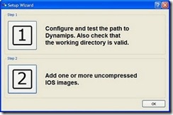
GNS3 Configuration Guide
What is GNS3 I hear you cry? Well, imho, it is the best tool on the market to practice router configuration without having an actual router in front of you.
What is GNS3 I hear you cry? Well, imho, it is the best tool on the market to practice router configuration without having an actual router in front of you.

Streamlined IPv6 HeaderThe IPv6 header has a new format that is designed to keep header overhead to a minimum.
VLSM – Variable Length Subnet Masking. Several new methods of addressing were created so that usage of IP space was more efficient.
Classful routing protocols strictly follow the subnet masks i-e. for Class A (8-bit prefix or /8)
Bridge groups provide a method to group two or more ports into a single broadcast domain
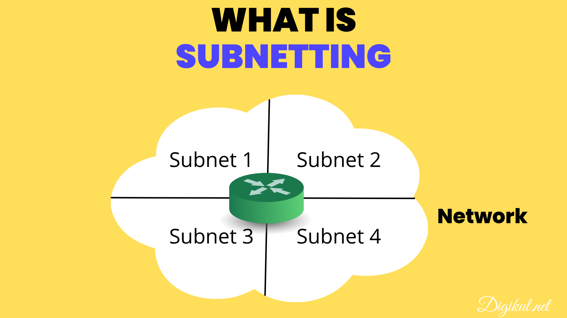
Question 1: What is the first valid host on the subnetwork that the node 172.
When you are trying to figure out the name for an IP address, Inside Local / Inside Global / Outside Local / Outside Global.
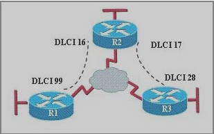
Question 1:The command frame-relay map ip 10.

The simplified easiest way to Understand Frame Relay
By David Rupu Xiao CCIE #24177
Waves – Wireless starts and ends with waves, specifically radio waves.
The Cisco Discovery Protocol (CDP) is a media- and network protocol independent layer 2 protocol
ACCESS LISTSAccess lists allow Cisco routers to function as a packet filter and are supported for several protocols.
Integrated Services Digital Network, a circuit-switching network used for voice
The OSI (Open System Interconnection) model is developed by ISO in 1984 to provide a reference model